Integrated circuit EUV technology innovation draws semiconductor blueprint
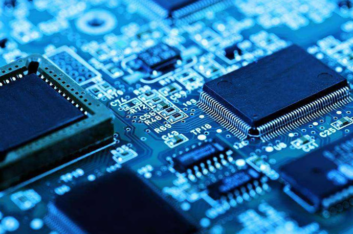
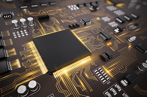
Semiconductor scaling (Scaling) is one of the hottest topics in the semiconductor industry. As most electronic components and storage units, including DRAM and other chip components, tend to be ultra-miniaturized, the demand for highly integrated technology is gradually increasing, and ultra-small chips will be able to store and quickly process astronomical amounts of data .
Today, the core of semiconductor scaling (Scaling) is a new generation of exposure technology - Extreme Ultra Violet (Extreme Ultra Violet, referred to as EUV) technology.
"Moore's Law is over" Semiconductor miniaturization technology is in a bottleneck
Semiconductor miniaturization has entered the 10-nanometer era, and the previous "Multi Patterning" technology no longer works. Because, in the 10-nanometer chip manufacturing process, the previous argon fluoride exposure technology (Argon Fluoride, ArF for short) has fallen into a bottleneck. To date, the semiconductor industry has followed the "Moore's Law" of doubling chip integration every 24 months. However, as the lithography process becomes more and more difficult, Moore's Law, which was once brilliantly used, will eventually be eliminated.
The photolithography process is one of the semiconductor manufacturing processes that use lasers to draw ultra-micro circuits on the wafer. The process of transferring the circuit pattern to the wafer is similar to the process of making traditional photos. Therefore, the English word "photolithography process" has "Photo". word.
"Photolithography" is a pattern transfer and copying technology, which realizes the appearance of an The shadow copy is transferred to the wafer. This formation of pre-designed patterns on wafers is a key process in semiconductor manufacturing. In this process, the fineness of the circuit pattern is a decisive factor for the competitiveness of semiconductor technology.
"Scaling", that is, reducing the length of the gates of transistors in semiconductor circuits, has always been regarded as the most important issue in the industry. The transistor switch is like a bridge connecting the source and drain stages, and it is the valve that regulates the current. Therefore, the shorter the length of the switch, the greater the number of electrons flowing from the source to the drain, and the correspondingly faster the circuit runs.
In recent years, semiconductor exposure equipment has developed rapidly, and all use larger lenses or short-wave light sources with high numerical aperture (NA). But existing liquid immersion argon fluoride exposure equipment (ArF) will reach its limit when the gate length shrinks below 30 nanometers.
DRAM chips up to 18 nanometers use multiple imaging technologies, but this will increase the number of processes, reduce productivity, and increase material costs, resulting in increased costs. When the number of processing steps reaches 500-600, it can be seen that the technology has come to an end. The only solution to this problem relies on short-wave light, drawing circuits with finer "slim strokes".


Principles and Characteristics of Quartz Crystal Resonators
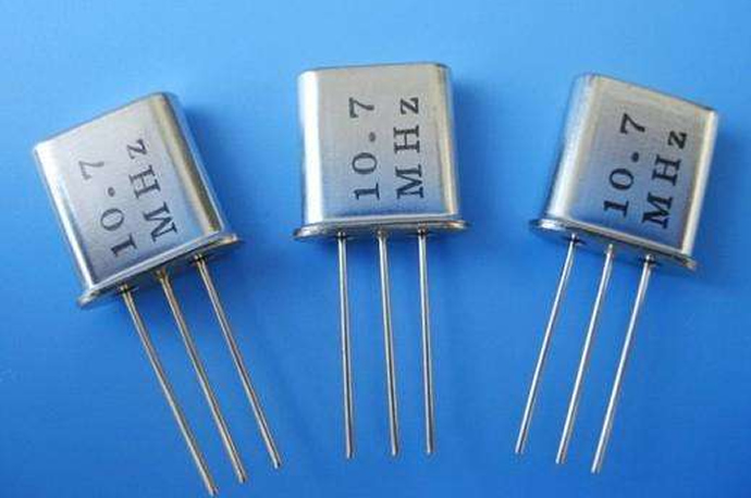
Quartz crystal resonator is an oscillator with high precision and good stability, which is widely used in radar, navigation, telemetry, radio, instrumentation and other fields, as well as frequency generators in communication systems, clock signals of data processing equipment and specific system reference signal.
The basic principle of quartz crystal resonator:
1. The structure of the quartz crystal resonator
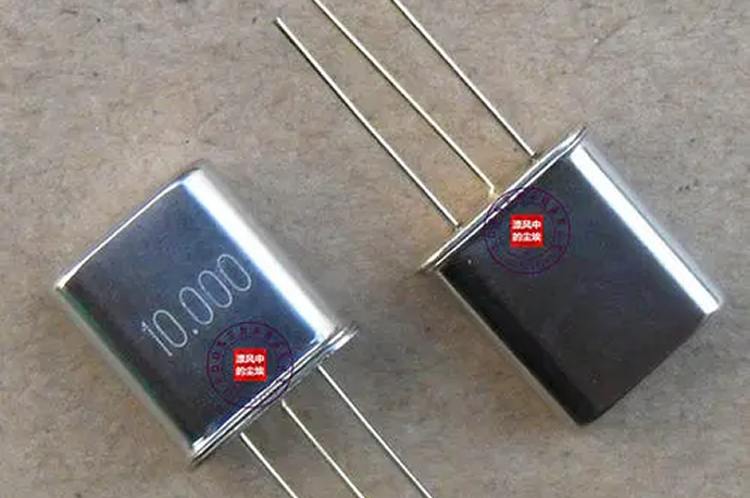
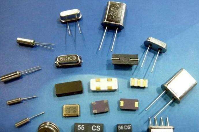
Quartz crystal resonator is a resonant device made of piezoelectric effect of time-responsive crystal (silicon dioxide crystal). Its basic structure is roughly as follows: a slice is cut from the crystal at a certain azimuth angle (referred to as the slice can be a square, a rectangle or a circle, etc.), and a silver layer is coated on its corresponding two surfaces as electrodes, Solder a lead to each electrode to connect to the pin, and add an encapsulation case to form a quartz crystal resonator, abbreviated as a time crystal or. Its products are generally packaged in metal casings, but also in glass casings, ceramics or plastics.
2. Piezoelectric effect
If an electric field is applied to the two electrodes of the crystal at the same time, the wafer of the quartz crystal resonator will be mechanically deformed. Conversely, if mechanical pressure is applied to both sides of the wafer, an electric field is created in the corresponding direction of the wafer, a physical phenomenon known as the piezoelectric effect. If an alternating voltage is applied to the two poles of the wafer, the wafer will generate mechanical vibration, and the mechanical vibration of the wafer will generate an alternating electric field. In general, the amplitude of the mechanical vibration of the wafer and the amplitude of the alternating electric field are very small, but when the frequency of the applied alternating voltage is a certain value, the amplitude increases significantly, which is much larger than other frequencies. This phenomenon is called piezoelectric resonance and is very similar to the resonance phenomenon of LC circuits. Its resonant frequency is related to cutting method, geometry and wafer size.
3. Symbols and Equivalent Circuits
When the crystal of the quartz crystal resonator does not vibrate, it can be regarded as a flat capacitance, which is called electrostatic capacitance c, and its size is related to the geometric size of the wafer and the electrode area, generally ranging from a few PF to several tens of PF. When the crystal oscillates, the inertia of mechanical vibration can be equivalent to the inductance l, and the general value of l is tens of mH to hundreds of mH. The elasticity of the wafer can be equivalent to the capacitance c, and the value of c is very small, generally only 0.0002~0.1pF. The loss caused by friction when the wafer vibrates is equivalent to R, and its value is about 100 . Because the equivalent inductance of the chip is very large, C is very small, and R is also very small, so the quality factor Q of the loop is very large, which can reach 1000~10000. In addition, the resonant frequency of the wafer itself is basically only related to the cutting method, geometry and size of the wafer, which can be fabricated. Therefore, generally speaking, the oscillator circuit composed of quartz crystal resonators can obtain higher frequency stability.


What are the characteristics of EMXO vacuum micro crystal oscillator?
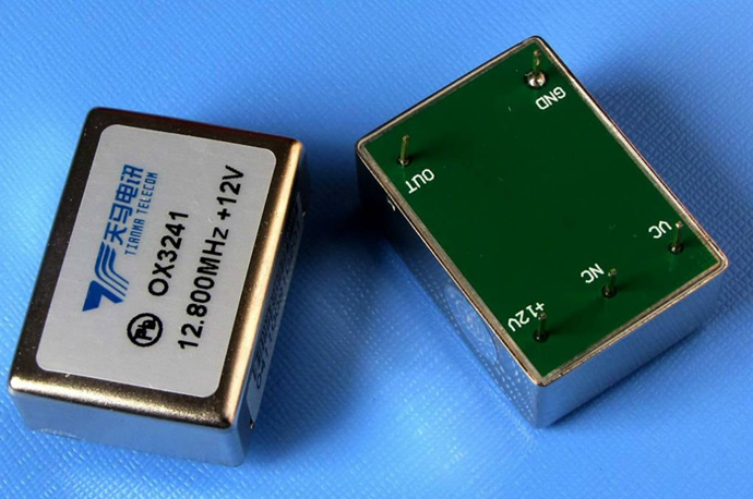
OCXOs (Oven Controlled Crystal Oscillators) are used when the frequency and temperature requirements are too stringent to be met by a basic XO (crystal oscillator) or TCXO (temperature compensated crystal oscillator). When using an OCXO, the temperature of the crystal and critical circuits will remain constant as the temperature outside the oscillator changes. Controlling the temperature inside the oscillator with an oven keeps the temperature constant. In an OCXO, changes in ambient temperature are sensed and then fed back to the oven controller, which is A constant optimum temperature is maintained continuously inside the oscillator housing. OCXO can increase the inherent stability of the crystal by more than 5000 times. The oven control system is not perfect, the open loop gain is not infinite, there is an internal temperature gradient inside the oven (oscillator), Whereas in a conventional oven, the circuitry of the oven casing is affected by changes in ambient temperature. 'pull' the frequency.
Compared with XO or TCXO, the temperature stability performance of traditional OCXO is greatly improved. For example, OCXO power consumption is greater than 200 times. There is also a size consideration. In ordinary OCXO, the crystal is packaged in a metal case, This is then put into an oven enclosure along with the temperature sensitive circuitry and then surrounded by thermal insulation. Then all of this and any additional circuitry is placed in a metal enclosure into a bulky package which becomes very difficult to miniaturize. In order to Overcoming these obstacles, the EX-380 series EMXO (Vacuum Micro-Oven Controlled Crystal Oscillator) was specifically developed to achieve OCXO performance while significantly reducing power consumption and packaging size


Some suggestions for crystal oscillator C1, C2 values
1. The crystal oscillator does not vibrate when it oscillates ------ a: The crystal oscillator load does not match the capacitance at both ends, causing the frequency deviation to be too large; b: The crystal oscillator itself has problems, parasitic & impedance value fluctuations & internal solder joints are not strong, etc.
2. The crystal oscillator can’t be installed on the board. It can be urged with electric hot air or removed and re-installed. The main reason is that the crystal oscillator load does not match the capacitance at both ends, causing the frequency deviation to be too large. Electric hot air is actually equivalent to changing the stray capacitance of the line.
3. The matching of the crystal load and the capacitance at both ends of the crystal -------- CL=(C1*C2)/(C1+C2)+C”
Where CL: load capacitance value of crystal oscillator; C1 C2: capacitance value at both ends of crystal oscillator; C”: line stray capacitance
The main function of the matching capacitor of the crystal oscillator is to match the crystal oscillator and the oscillating circuit, so that the circuit is easy to start vibration and in a reasonable excitation state, and also has a certain "fine-tuning" effect on the frequency. For the MCU, the key to correctly select the matching capacitor of the crystal oscillator is to fine-tune the excitation state of the crystal to avoid over-excitation or under-excitation. The former makes the crystal easy to age and affects the service life and causes the EMC characteristics of the oscillator circuit to deteriorate, while the latter is difficult to start vibration and work. It is also unstable, so it is very important to choose the crystal matching capacitor correctly.
4. The time deviation of the 32768HZ crystal oscillator: the deviation of the time is mainly due to the deviation of the frequency. The frequency deviation of 1PPM is converted into a day time error of 0.0864S. Then if the time error is required to be accurate, it is best to weld the capacitors at both ends of the crystal oscillator according to the normal ratio. At the same time, ask the crystal oscillator supplier to help find the best 0-error PPM value through QWA testing, and specify the supply according to the 0-error standard. frequency range.
5. Welding of 32768HZ crystal oscillator: 1). When encountering, the shell of 32768HZ crystal oscillator is welded on the board to achieve signal shielding and anti-interference. As a result, the solder joints inside the crystal oscillator will be melted due to too long soldering time, and the internal structure of the wafer will be tilted against the shell and short-circuited. The best way is to have two pinholes on the PCB and use copper wire to bind the crystal. Or use a rubber binder. 2). The crystal oscillator bends freely when bending the feet. The best bending is to pinch the outer casing of the cylindrical crystal with your fingers; use tweezers to clamp the lead 3mm above the bottom of the crystal base, and use tweezers to clamp the bent lead at 90°, do not pull the lead too hard. Pulling the lead wire forcibly may cause the glass at the root of the lead wire to break, resulting in air leakage and damage to the electrical performance. If the crystal is leaking, it is basically unusable.
6. Because of the dirt such as solder resist during welding, choose to use ultrasonic cleaning of PCBA board: ultrasonic cleaning or ultrasonic welding will affect and damage the internal structure of the quartz crystal or even the chip is damaged.
7. The start-up time of the crystal oscillator is long, and it will start to oscillate when it is turned on and off, and the finished battery is not durable. This is mainly caused by the resistance of the crystal oscillator is too large.
5. Welding of 32768HZ crystal oscillator: 1). When encountering, the shell of 32768HZ crystal oscillator is welded on the board to achieve signal shielding and anti-interference. As a result, the solder joints inside the crystal oscillator will be melted due to too long soldering time, and the internal structure of the wafer will be tilted against the shell and short-circuited. The best way is to have two pinholes on the PCB and use copper wire to bind the crystal. Or use a rubber binder. 2). The crystal oscillator bends freely when bending the feet. The best bending is to pinch the outer casing of the cylindrical crystal with your fingers; use tweezers to clamp the lead 3mm above the bottom of the crystal base, and use tweezers to clamp the bent lead at 90°, do not pull the lead too hard. Pulling the lead wire forcibly may cause the glass at the root of the lead wire to break, resulting in air leakage and damage to the electrical performance. If the crystal is leaking, it is basically unusable.
6. Because of the dirt such as solder resist during welding, choose to use ultrasonic cleaning of PCBA board: ultrasonic cleaning or ultrasonic welding will affect and damage the internal structure of the qu


The production process of quartz crystal resonator
To produce a quartz crystal resonator with good performance, in addition to reasonable design and excellent raw materials, the production process will play a decisive role. Different types of quartz crystal resonators have different production processes.
Quartz crystal resonator chips come in three common shapes: round, square, patch-specific, or rod-shaped (also square, but smaller). Different orientations have different piezoelectric properties, elastic properties and strength properties, and the performance of resonators made from them will also vary. The existing cutting methods can be divided into AT-CUT, BT-CUT, CT-CUT, DT-CUT, FT-CUT, XT-CUT and YT-CUT; Determined according to the actual situation. If the temperature characteristics are good, AT-CUT should be used, and if the frequency required by the crystal oscillator is high, BT-CUT should be used. The dicing pattern, geometry and size of the wafer determine the frequency of the crystal oscillator.
The specific steps for producing quartz crystal resonators are as follows:
First, embryo screening. Due to the large cutting angle error of the quartz crystal resonator blank, it is necessary to use an x-ray orientation instrument for angle sorting before rough machining. Then select the appropriate angle of rough embryos for processing according to the needs, that is, sticking strips, cutting seed crystals, rounding, etc.
Then the grinding process is generally divided into coarse grinding, medium grinding and fine grinding. Rough grinding is mainly about cutting the angle and thickness of the wafer, while medium grinding and fine grinding are fine-tuning of wafer thickness.
After grinding, in order to ensure the surface quality of the quartz crystal resonator wafer and the stability and reliability of the crystal in use, the wafer is polished and cleaned accordingly. The thicker the wafer, the greater the impact on the startup performance and resistance of the crystal, so it is more effective to remove the deep etching of the loose layer on the wafer surface caused by grinding.
The installation and dispensing method is to slowly place the electrode-plated timing sheet between the two metal sheets of the belt support, so that the two metal sheets with slotted holes can tightly clamp the timing sheet, and then place the timing sheet on the electrode. A layer of conductive glue is applied to the contact with the metal sheet, so that the electrode film can contact the metal sheet through the conductive glue on the edge to generate electrical connection.
Adjusting the resonant frequency of the quartz crystal resonator to meet the design requirements is a key process in the production of FM crystal oscillators. Different types of crystal oscillators have different frequency modulation methods, such as vacuum coating frequency modulation and polishing wafer frequency modulation. For the production of crystal oscillators with low added value and high cost requirements, the frequency modulation process of polished wafers is often used.
After that, the process of encapsulation, printing and finished product measurement is carried out.
With the continuous expansion of the information industry and electronic industry in various countries, the application scope of quartz crystal resonators is still expanding, which drives the continuous growth of its market size. At present, the market has a great demand for crystal oscillator products with high precision, high frequency, high stability and low power consumption. Moreover, with the development of ultra-thin, miniaturized, and functional integration of electronic products, crystal oscillator products will also be upgraded to miniaturization, chipization, and integration. Therefore, the production technology of the crystal oscillator industry should still have a lot of room for improvement.


New Trends in New Crystal Oscillators
Quartz crystal oscillators are high-precision and high-stability oscillators, which are widely used in electromechanical devices that provide stable clock signals in various electronic applications such as audio, security monitoring, and communication systems. Processing devices generate clock signals and provide reference signals for specific systems.
The demand for quartz crystal oscillators is growing, and quartz crystals operate in the frequency range from tens of kilohertz all the way up to hundreds of megahertz. Crystal oscillators are known to be superior to ceramic resonators because of their higher stability, higher quality, and lower cost and more compact size. They can be found in a wide range of products in military and aerospace, research and measurement, industrial, automotive and consumer products. Key players include Epson Corporation, Nippon Denwa Corporation (NDK), Osquark (ADVA), Murata Manufacturing Co., Ltd., Great Vacuum Corporation (KDS), Rakon Ltd., River Eletec Corp.
However, while quartz crystals are inexpensive to produce and continue to find many applications in clock circuits, quartz crystals are increasingly being challenged by more advanced devices such as microelectromechanical systems (MEMS) resonator-based clocks and oscillators challenge. In fact, some estimates suggest that MEMS offer 10 times better reliability than comparable quartz oscillators.
KDS launches new oscillator
In October, KDS, a Japanese manufacturer and seller of crystal devices and resonators, introduced its new DS1008J series of differential output crystal oscillators (DOCOs) in Munich. Produced as a solution to the rapidly growing data flow through mobile networks and big data in recent years, the company claims the devices are the "smallest and thinnest DOCOs" in the world. Most differential output crystal oscillators on the market are 7050 and 5032 sizes. The 1008 size of KDS is much smaller than regular products currently on the market. Other recent developments from KDS include the DS1008JN KDS low-voltage clock crystal oscillator (1.2V). Applications include mobile communications and short-range wireless modules; wearables and automotive multimedia devices.
Nihon Dempa develops highly reliable crystal oscillator
In August, the Japanese company NDK Co., Ltd, one of the largest quartz crystal companies in the world, announced the development of a new NT2016SJA crystal oscillator for mobile communications. It claims the device can withstand severe vibration and shock, and as space-use electronics mounted on satellites and rockets, is highly resistant to radiation in the space environment. Crystal oscillators feature ultra-low phase noise, support low supply voltages, and are ultra-compact and lightweight.


Previous
1
2
Next
CONTACT INFORMATION
OFFICIAL ACCOUNTS

ONLINE MESSAGE
客戶留言
描述:
Copyright © Tangshan Huixun Electronic Technology Co., Ltd. All rights reserved Power by 300.cn Tangshan
代碼
發布時間:2021-12-14 17:22:59

